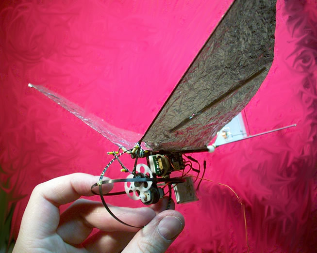
Quick Silver (The Electric Bat)
better suggestions for a name (still) considered
VIDEO
Notes on the video: It was taken off VHS hence the quality. No one expected the model to fly (I showed them) hence the lack of take off shots. The ending is rather dramatic but on closer examination of the raw footage the model was on an even keel before leaving the shot. And in reality it did just keep flying. Boing!!
The project began after considering building a really small machine much like Matt Keennon's Microbat and deciding a better bet might be to use an existing rubber design as a basis for a larger model to start with. It seems great minds think a like as you will see in this thread here.
After seeing that I sat down at the PC, made some design decisions and drew a few parts in Rhino to be cut out on my little CNC. That sounded straight forward didn't it. OK it took longer than an afternoon. With flight tests only once a month and some missed flight sessions the development speed has been a little on the geological side.
The basic spec:
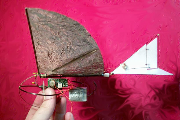
Wingspan: 12"
Weight: 17g
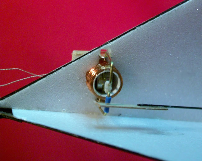
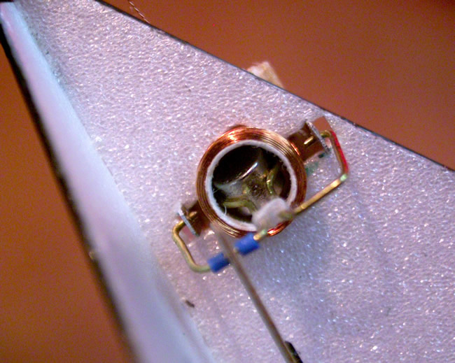
Motor: KPOO, or M20LV a 10mm diameter hot brushed motor.
Radio: JMP actuator combo.
Battery: 1 X 145mAh LiPoly cell.
Gear ratio: 33:1 using Didel gears in a custom gearbox. Bushes
are Didels and shafts are hardened drill blanks.
"Crank ratio": 4:1 as per the FreeBird this model is
based on. The crank geometry is a little different.

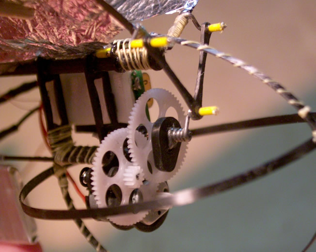
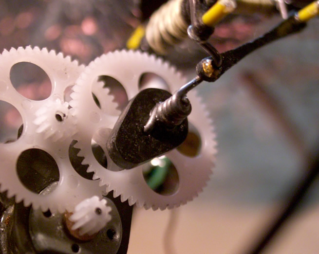
Here is an overview of the flapping mechanism. The first thing to notice is that it is scaled down in comparison to the FreeBird2, the crank is much shorter and everything is more compact. This may not have been a good idea in terms of bearing load but I like the look of the model. The motor is a push fit in a piece of custom made carbon tubing and this in turn is glued into two CF plates that each hold the brass bushes. The two Didel gears then form a 33:1 gear ratio to the crank output. The crank is a double crank as per the original FF rubber design. This was perhaps not the best way to go about things but at the time my knowledge of flappers was limited. What I did know was that I did not want the meshing of the gears to change because of the force applied to the crank. To prevent this I used drill blanks for the shafts, this barely bends and never breaks. However you can't bend a crank from it!! The solution suggested by Peter Frostick was to use a technique sometimes used by FF rubber guys to drive props. The crank was made with a spring at one end such that the force applied to the crank tightened the spring to grip the shaft. A small tab on the end of the spring would also engage with the gear. Unfortunately the gear is a little too thin for such engaging tabs and the spring effect not quite up to the task especially in the early days with a heavy throttle thumb.
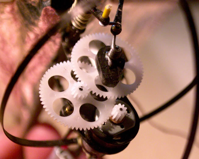
To beef it up I borrowed an idea from the Didel prop hubs. These engage with the small gear in the centre of the spur to transfer the power. Mine is made from CF and details of its manufacture can be seen here. To make it even beefier the end of the spring goes through the crank driver and engages with the gear as well. The cranks are CNC cut 0.8mm thick CF sheet bushed with brass tube. All these parts are retained with cable outer which is also dabbed with 5min epoxy as these things know how to work things loose. The gearbox is removable and is a push fit on to the sub fuselage, this joint is also 5min epoxied but can be removed when required. The sub fusy hangs on a couple of 0.8mm CF stand offs. One other modification is the dropped wing pivots, the point at which the conrods connect to the wing spar has been lowered to avoid a nasty toggling action at the suggestion of Peter again. This required a change in conrod lengths and this was done by trial and error while trying to get a fair amount of dihedral in the flap.

Flying
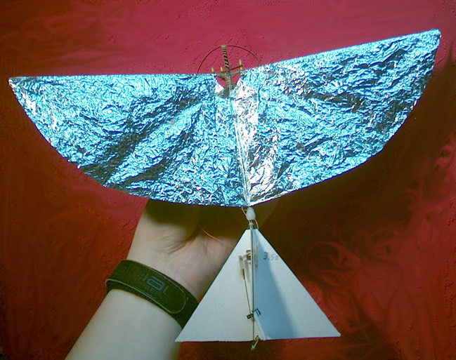
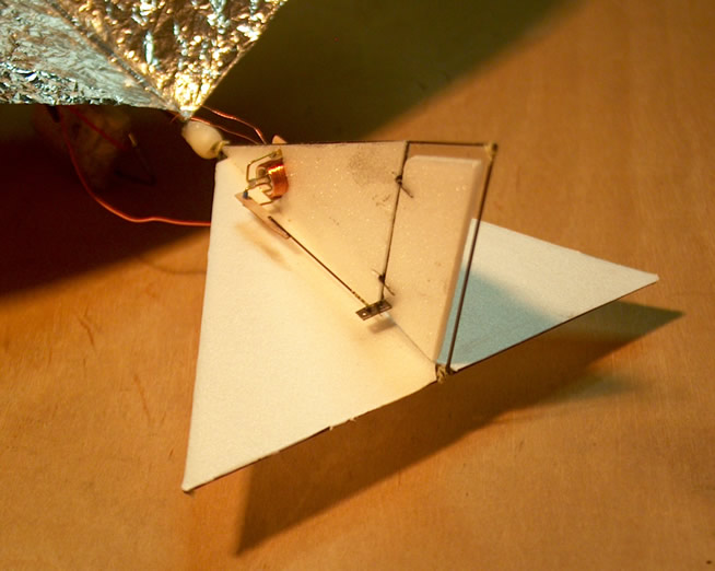
I had some encouraging flights right from the offset but they were only that. Initially the crank geometry meant I was loosing a lot of power due to the toggling action (which I countered with a stop) but the stability was nice. It was hard to keep in trim as well, as in the early stages it was throttle only and the tail was held by a length of ali tubing. The crank geometry was changed and there was a good improvement with some better flights, including climbing flight however I was dogged by mechanical failure. This was fixed with the crank driver and gluing of all parts involved in the gearbox. Later it was improved further with a beefed up bumper and the gearbox stiffening rods. The tail was replaced with a CF rod frame and 0.5mm depron covering and the ball joint added.
At this point I got some very encouraging flights. Still a few mechanical problems but mainly crash induced. There was one thing for it and that was control.
Once the ornithopter is basically trimmed by adding tip weights or crank tweaking or both the most important setting is the elevator. The hole tail was cranked up much further than seen in these pics but is was critical for good flights. Too much and the flight it stally and control is poor. Two little and the flight is very short indeed ending on the floor. Just right and the model moves purposely through the air. I'll add trim tabs to achieve this later or perhaps elevator. Anyway I tend to give the model about half throttle on the hand launch and give it a fair heave ho. I then throttle up or down depending on the elevator trim situation. When it was right it was a doddle to fly. Very controllable and capable of figures of 8 easily in the smallish hall it was flown in. It reached the ceiling on more than one occasion and I had the throttle back, not something I ever expected. The hardest part is orientation, it made me feel a little sick after a while. Oh that was 3min and 50seconds by the way.
What next? Well a 6mm pager motor and IR and there are plenty of other things to try as well as general improvements.
Cheers,
Graham