First off please contact me if you have converted an MF70, let me have some pics or links. Share your experience and tips and I'll shove them on the page.
NEWER, see some pics of the enclosure/stand on this page
EVEN NEWER, some stuff in the grey boxes.
SUPER NEW, lowing the backlash
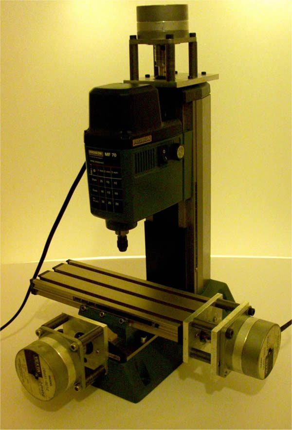
Here are some pictures of my conversion of a Proxxon MF70 micro milling machine. I had been looking to buy a small milling machine for CNC conversion for a while but my budget is limited. Then I saw a post on the CAD_CAM_EDM_DRO yahoo group about the conversion of this tiny Proxxon mill. The cutting area is small (about 2"x5"x2") but it is a sturdy little machine with a spindle that will provide 20,000rpm to cutters up to 3mm in diameter. This was perfect for me and costs about £200.
If you would like to see details of the other conversion carried out by Tim Goldstein, then please have a look here. There is also a lot of other useful stuff on his website including larger millls by Sherline suitable for conversion or CNC ready and all with excellent discounts. Tim will also soon be selling these little fellows so if you are on the other side of the pond you might want to contact him.
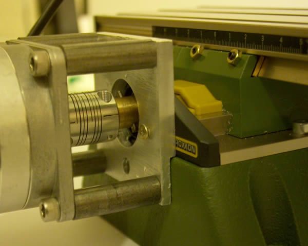
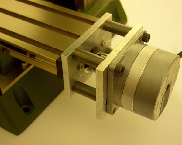
One thing I should mention is although I did have access to a Bridgeport milling machine to make my adapter plates non of the parts are so critical that they could not be made by hand. A lathe is probably the only real requirement to make the brass adapters. The motor posts can be made from threaded rod as was done by Tim.
My conversion is almost identical to Tim's apart from a few minor points.
How to take the handles off
Whether you decide to create a longer leadscrew and have the stepper at one end and the handle at the other or you decide to just ditch the tiny handles you will need to get them off. It has mystified many, here is how:
1. Remove nut from far end of leadscrew.
2. Unscrew leadscrew from the machine.
3. Slide the graduated scale away off the handle, this reveals the rolled
locating pin.
4. Carefully tap this out with some sort of punch/drift.
5. Your done
Some CAD
Here are my drawings, you may wish to do things differently but it might save you some measuring time, sorry they are not very well formatted etc:
Adapter plate CAD dxf format
Adapter plate CAD pdf format
Oh, this is not for commercial use unless you ask.
NEW: Lowering the backlash:
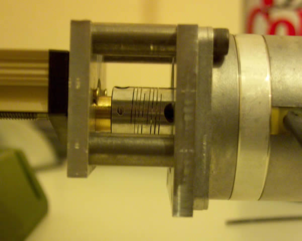
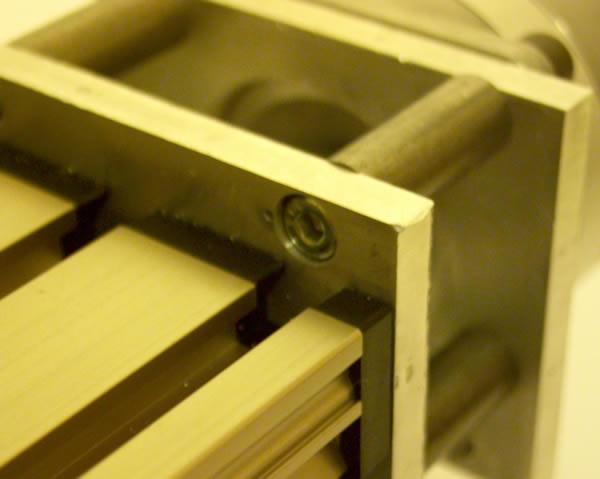
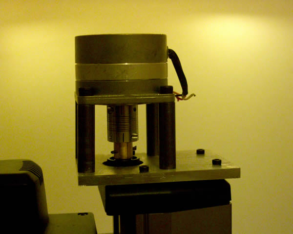
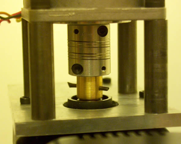
I actually did this because I was chasing an error that was losing my steps, in the end it turned out to be my old laptop but it was nice to tweak the mechanics and get everything oiled and running smoothly. The nuts use on the table are delrin and they provide very low backlash operation, its also not much of a trouble to replace them if they get worn. The only real source of backlash is end float of the leadscrew. The screws are held in tension by the brass adapter that replaces the handwheel at one end and a nut at the other, washers act as thrust bearings. The problem is, if you tweak out the end-play the friction rises dramatically. To get around this I have used some 6mm ID flanged bearings I had lying around. They simply replace the washers and reduce the amount of friction massively, even if only added at one end. Radial bearings have an axial load capacity of about half of the radial capacity, that is normally huge so nothing to worry about there. I literally just plonked them in, though I did use a bit of epoxy just to hold them in place so they can move laterally.

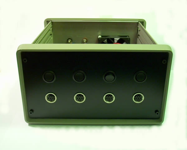
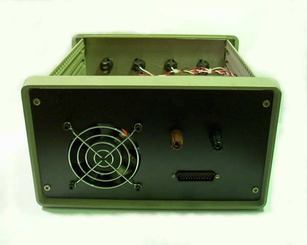
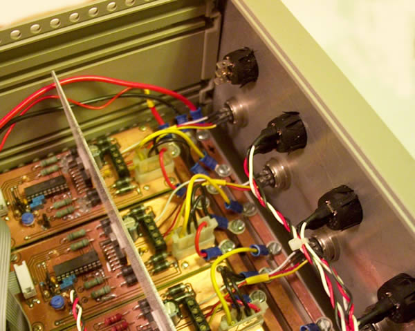
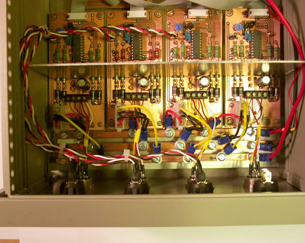
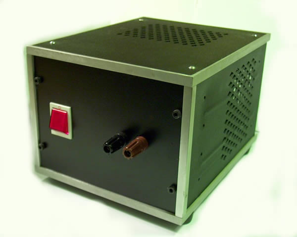
I have built mine from the plans on Hans Wedemeyer's website. This is a 2 amp bipolar chopper driver. This means that it limits the current to a maximum of 2 amps and drives bipolar or two phase motors. These are generally better than unipolar motors but are still cheap as surplus (try Ebay), mine were about £5 each. You can also buy a three axis bipolar chopper kit from Dan Mauch at Camtronics. I can vouch for Dan as a very easy person to deal with after buying his EDM plans and also the chopper driver kit for my Dad. Both came in less than a week. There is also another similar unit by Xylotex that seems very popular and I know are nice and compact as well as doing up to 2.5A.

efore I start taking about the trials and tribulations of milling I should mention the software; there are generally three stages to go through from idea to object and three separate software packages. Some software especially hobby stuff may include 2 or even all three stages in one package but I used three separate packages.
CAD: This is where the item is drawn. Depending on what you are making the drawing may be 2D or full 3D. I used Rhino3D, it is EXCELLENT!
CAM: The drawing is imported into this package and a set of tool paths are defined. For example you might want to do a roughing pass with a 3mm ball nosed cutter followed by a finishing pass with a 1mm cutter and then a contour cut with a routing bit to cut the part out. It is this software in which tool types, diameters, speeds and feeds are defined. The output of this software is G-code. These are text commands including coordinates that define the moves the machine must perform, for example linear/circular interpolation, drilling cycles etc. I used Mastercam9, this is not a hobby package and I only have occasional access. I am still looking for the right hobby package to buy for home use but there are plenty out there to choose from.
Aside: post processors: Most CAM programs have an internal file format that they use to define the operations. This is then "posted" to gcode to match the specific machine used. This is another reason why the hobby software is probably better as it is bound to contain a fairly generic post that will work with the machine control software you choose.
Motion control: The final piece of software takes the gcode file and translates it into pulses on the parallel port. Each axis has 2 pins, one step and one direction and it just steps and changes the direction of each axis as necessary. The software has other features such as jogging to allow set up but is really quite straight forward. I use TurboCNC which is shareware ($20 to register). You can download it for free and use it as long as you like but I do recommend registering as you get the source code and it is worth rewarding a job well done if you ask me.
The first cuts are the deepest:
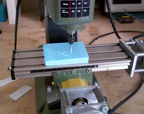
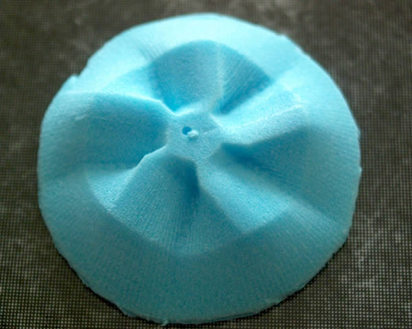
While waiting for time and inclination to finish the driver boards off I spent some time playing with Rhino3D and drew one or two things I thought would be nice to mill. One of these was a mould for a carbon fibre ducted fan. This was the first thing I milled and here it is rendered in blue foam. For those who are not familiar with it, blue foam is used to insulate floors etc. and is great for making models and for mucking about with milling things. Perhaps not as good as machining wax but very cheap and I had some. The fan pictured was milled with a 1mm square ended mill going straight to the finish pass. The tool paths were radial although that is a bad idea as the resolution gets worse as you go out to the edges. Still, I was happy.
Boxing Clever
Its a small mill but it was still taking up bench space and it kicks out some serious dust when milling at times. I needed some form of trolley and enclosure.
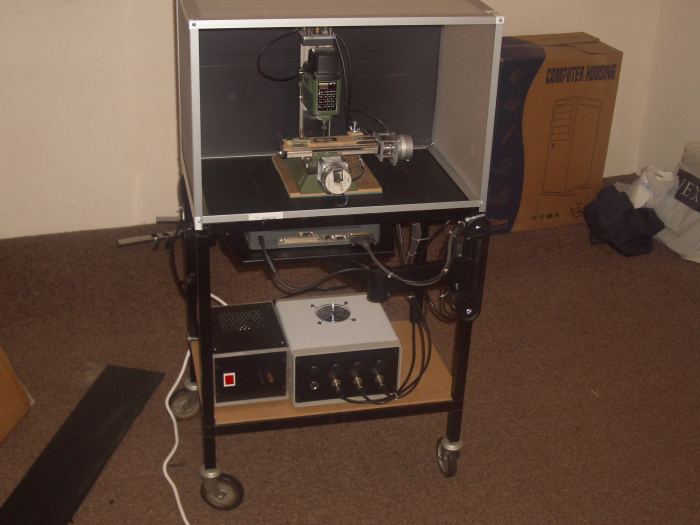
The trolley is a skip rescue job with a new mdf shelf. The frame of the enclosure is light weight aluminium angle bolted together. The back and sides are Correx, some of which is clear to let light in. It still needs a door though.
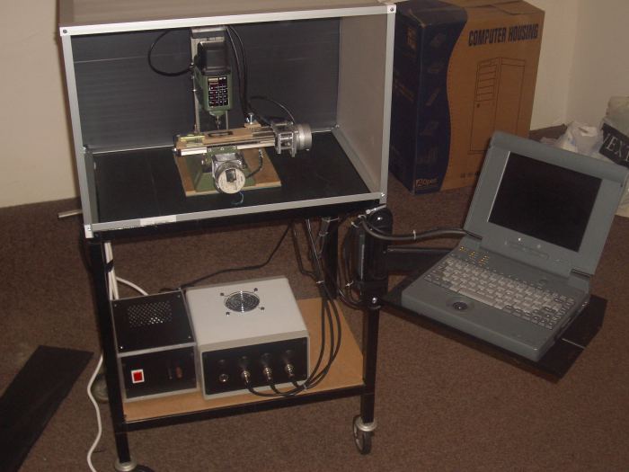
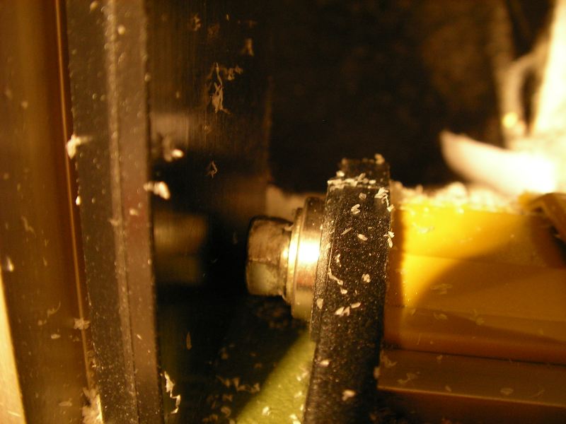
I nearly threw this monitor bracket away, I'm glad I didn't. The enclosure looks much better full of delrin chips!
The end, or is it:
I hope to have more from my computerized slave and some other planned machines in the future so watch this space (now I know nothing will get built).
Graham Stabler