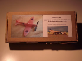
Milling half a Spitfire (update, now a whole one!):
This fuselage was drawn in Rhino3D from FF plans and then milled in Styrofoam FM (a white foam like blue foam but better). The two halves were later hollowed and assembled into an excellent FF rubber Pistachio model, built and flown by Peter Frostick at the indoor FF nationals (see the bottom of the page). The model flies great which is down to Peter's skill rather than mine, I just save some labour.... for him ;)
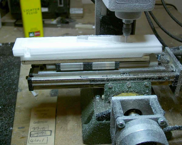
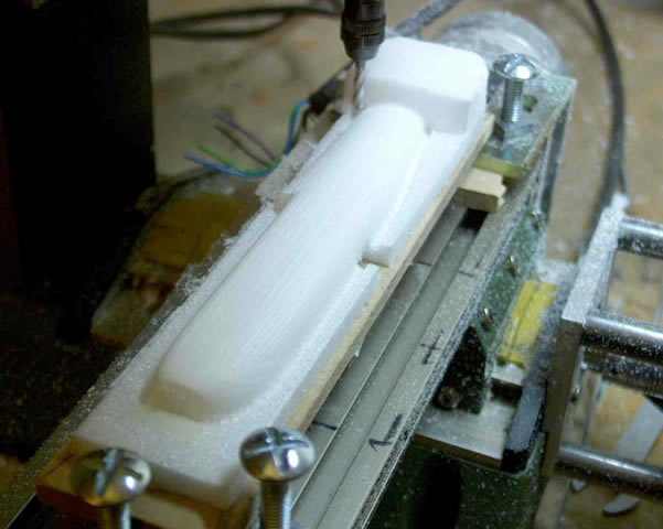
The first section being milled. The slide (two silver bits with black ends) used to extend the travel is over to the left. After this section is milled the slide is moved over to the right (about 44mm) so that the mill can get to the far right of the foam block. The foam (Styrofoam FM, "super blue foam") is doubled sided taped to a 6mm Depron sacrificial base. This allows the cutter to be zeroed on the top of this plate and means that once milled the the parting line for the fuselage half is in just the right place as the cutter can go below the zero. This sliding process was far from trivial as I didn't have a dial gauge, all the squaring up was done with a drill blank in the collet and keen eyesight!
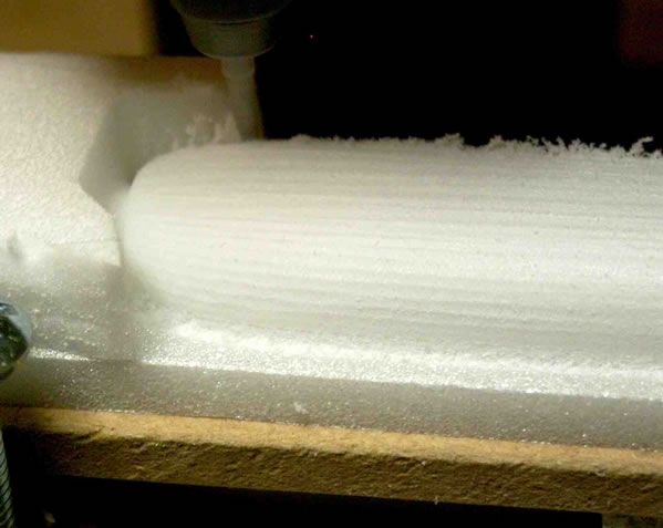
Finishing passes using "flowline" milling. The cutter (a 3mm ballend) follows the line of the fuselage (like the lines in a planked fusy) rather than just cutting parallel. This seems to be a really nice way to do it and it allows you to define a max scallop height rather than a step over. This is odd because certain areas need the tool paths to be closer than others to get this scallop height. It has a sort of "started so I'll finish" attitude so the worst scallop you see is 0.2mm (in this case) and the best is a near perfect finish.
A close up of the milled fuselage:
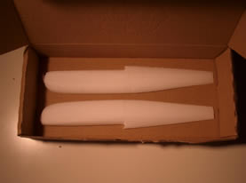
The finished article. It looks odd because I had to use gamma correction, otherwise it was totally saturated.

Now the other half :)
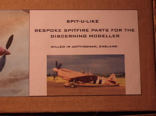
Update, well I did the other half and they were dutifully sent off to Peter who made this:
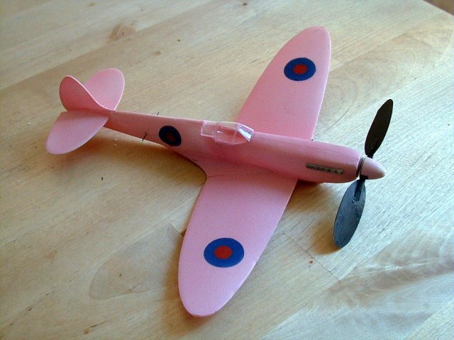
Super isn't it!! And the colour IS scale. The model flew for 90 seconds at the Nats.

Conclusion 1:
What a great way to make a model, no screwing up of the eyes to get symmetry and no need to be near at least one half of the dust making process.
Conclusion 2:
I need a bigger mill :)
Conclusion 3: Or a better method!! (update 6th June 2004)
Didn't seem right that Peter should have all the fun but setting up the slide was not much fun at all. So I am now using a manual rotary table and intend a fleet of warbirds to be powered by pager motors.
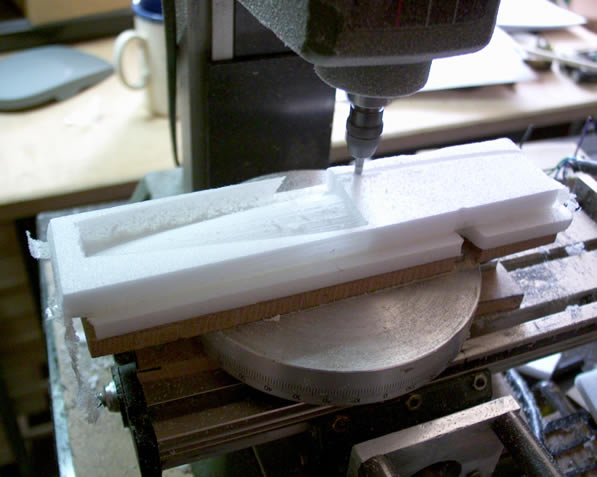
Here is the mill beginning the second half of the fuselage. The foam is taped to a depron plate again and this in turn taped to the MDF bed. The rotary table is bolted to both MDF plates and the lower one bolted to the bed of the mill. Quite straightforward. My supertip (I forgot about from last time) is to make sure that none of the double sided tape used to hold the foam lines up with the outline of the fuselage. If it does then you will have problems as the tape sticks to the cutter and clogs the flutes.
The milling process is quite straightforward, I altered the cad so that is is now in two halves that slightly over lap. I then produced an NC file for each half. I run one and then move the cutter back to 0,0 in x and y (that is very important!) I then rotate the table by 180 degrees. The second file is loaded but before running it I invert the directions of the x and y coordinates. That way although the machine thinks it is shooting off to the left to mill the front of the fuselage it actually shoots off right and stays within the envelope of the mill.
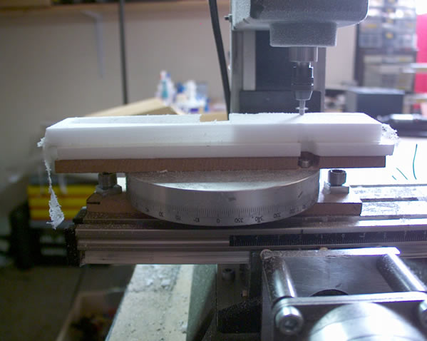
Another shot of the milling process. The table has a simple vernier to align it. You may also notice that it is upside down. This is to ensure that the locking screw (just below the milling cutter in this pic) is accessible.
As an aside my method of zeroing the mill on the centre of rotation (which is essential) was to temporarily tape an mdf block to the bed of the table and hover a sewing needle held in the chuck over it. By turning the table by hand and looking I could get the point to within 0.2mm, after that I made a tiny dot by lowering the Z, then lifted it again and rotated the bed by 180 before repeating. I then moved the needle tip to the mid point of those two points. Using a pocket microscope I got it pretty near central. I need a dial gauge!!
Just for a bit of fun: