Touchprobe:
This was supposed to be my first useful milling project. It is based on conceptual drawings that can be found in the files section of the CCED yahoo group, these in turn where based on the Renishaw patent.
Touch probes can be used for two operations. One is to find edges and the center of holes etc. as well as tool setting; the other is as a means to digitize a 3D object. That is to produce a 3D computer model of the object.
It is the latter that I intended to try. Touch probes are basically switches, I originally imagined a simple plunger and micro switch that would be held in the spindle of the mill (not spinning) and lowered on to the object. The signal from the probe would tell the computer when to stop lowering the probe and once contact was made the x,y and z coordinates could then be stored.
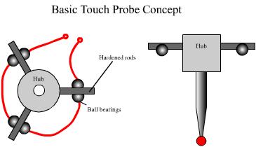
After some posts to the CCED group I discovered that most probes used commercially are more sophisticated than that. Firstly they trigger even when the surface is hit from the side. This is good for centre and edge finding but also for digitizing surfaces with steep sides. The most popular method used to give this functionality was developed by Renishaw originally. The principle is quite simple, the probe ( with a hardened point or ruby ball tip) fits into a hub and from this hub extend three hardened rods. These in turn sit on hardened balls. The rods are electrically insulated from each other but do of course make an electrical contact between the balls they sit on. There is an internal circuit which includes the balls and rods as switches in series. The hub with its rods is held in contact with the balls by a spring. The basic concept can be seen in the image below.
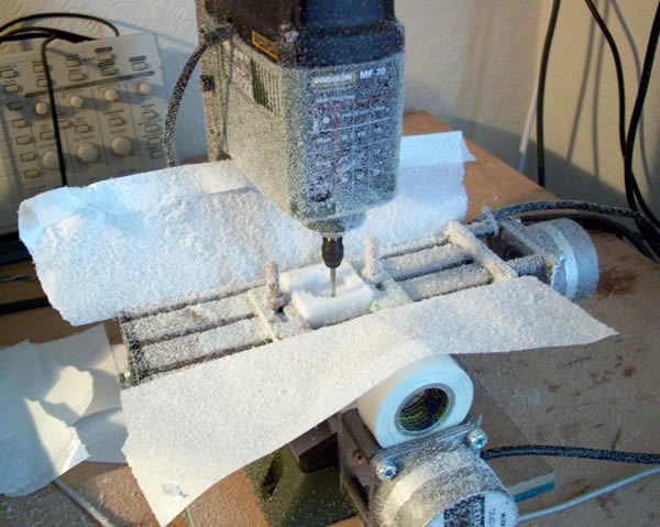
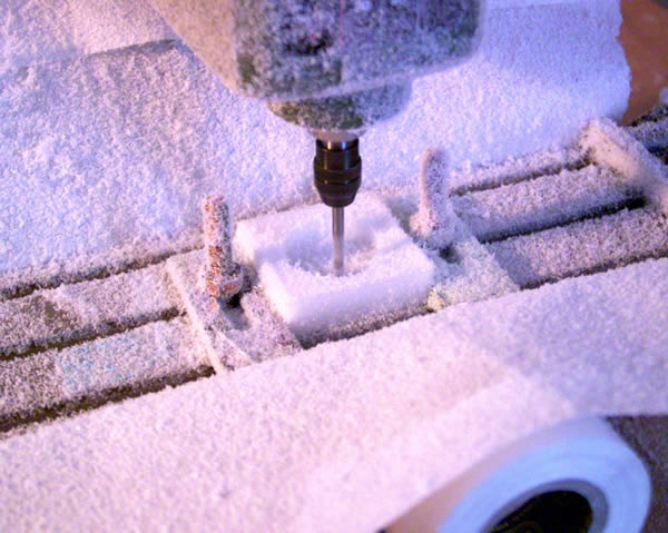
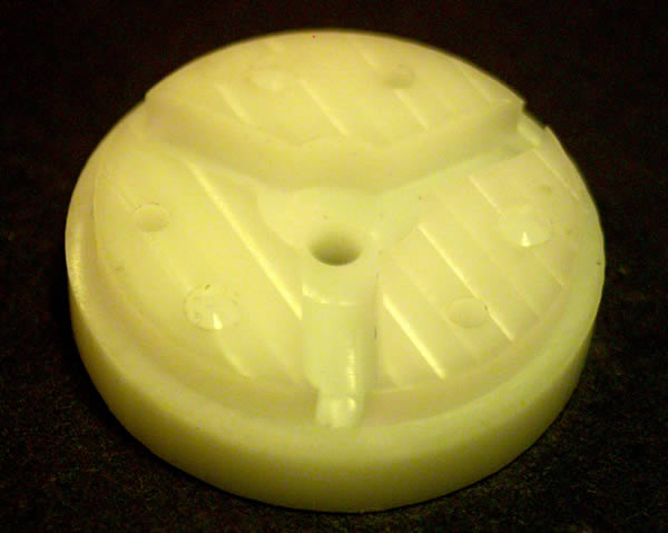
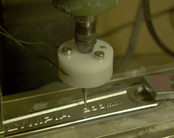
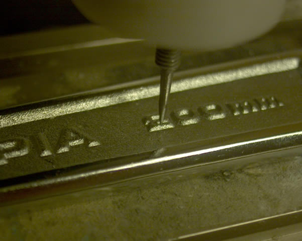
Here is the top or bottom (I forget) of the touch probe body being milled. The white sheets are replacement sticky stuff for a lint remover. I stuck them to the sides of the bed to collect some of the copious amounts of dust produced. I need a vacuum but it is low on the todo list.
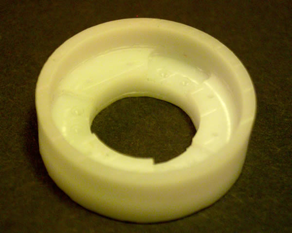
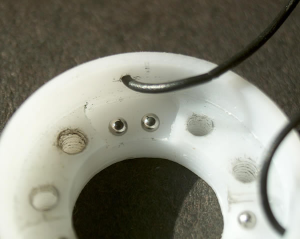
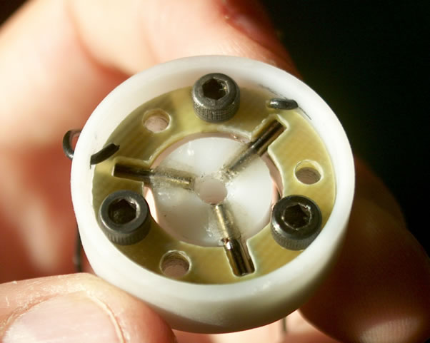
On the left is the bottom of the touch probe assembly. You can see three pockets around the outside and in each of these two small holes. These are to accept 2mm loose ball bearings.
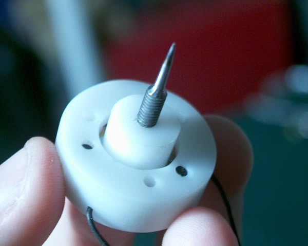
On the right is the lid. It makes a nice fit with the bottom which is encouraging and does little more than hold the shaft that goes into the spindle and a spring that presses the three rods down onto the balls.
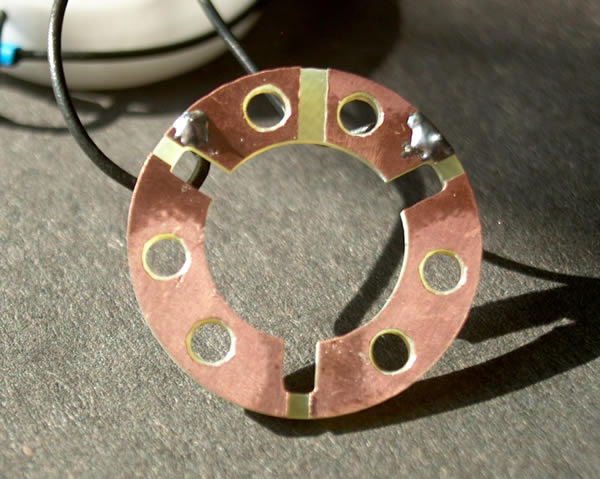
The probe is now ready for the hub assembly. This was again milled from sheet and to avoid the use of a rotary table slots were milled to accept the 2mm hardened steel rods (drill blanks) which were then glued. To ensure correct alignment the rods were glued in place with the probe positioned as shown but placed on a sheet of glass. This provided a flat(ish) surface to ensure the rods were on the same plane. They were kept long and a print out with 3 pairs of lines at 120 degrees to each other was produced to ensure the correct angular alignment. After the glue was set the rods were carefully trimmed (with a dremel) and more glue added to pot the rods in place.

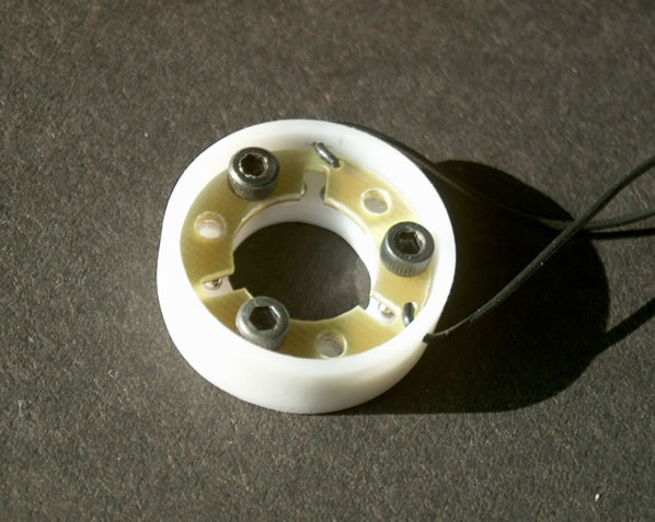
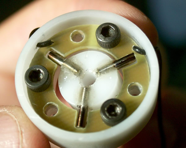
Next you can see the hub seated on the ball bearings. A circuit is now made between the two wires from PCB to ball to rod to ball ... On the right you can see the hub tipped as if the probe has hit an object from the side. This is hugely exaggerated as the probe will stop moving as soon as the circuit is broken. The actual tilt on the hub would be hard to detect by eye. Whether the probe tilts or lifts will depend on the surface being probed and on the operation being performed. Digitizing a flat surface will tend to cause the probe to lift where as a curved surface, especially one with steep sides will tend to cause a tilt. In reality I suspect most are more of a tilt as even when probing a flat surface it is most likely that one ball to ball circuit will break before the other two.
Probing:
To get started I used TurboCNC's built in probing routine. The probe was connected to one of the home switch inputs on my driver board and this was configured as the probe input. You then simply type in the command:
G32 Xbound Ybound Zbound Idiscretization Ffeed
Where Xbound, Ybound and Zbound are the boundaries of the area to be probed i.e. the probe will plunge to a maximum depth of Zbound and cover the area Xbound by Ybound. The gaps between the plunges is determined by Idiscretization and the feedrate by Ffeed so typing
G32 10 20 5 0.2 100 will probe a 10mmX20mm area to a max depth of 5mm with a 0.2mm stepover and a feedrate of 100mm/min.
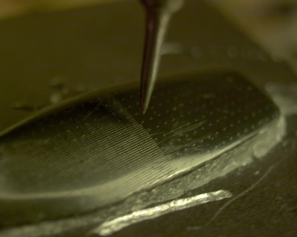
Below you can see the probe in action for the first time. The probe's
3mm shaft is held in the mills collet chuck. The first thing I scanned
was a portion of a spanner. Don't ask me why, I just couldn't find anything
else to digitize! One thing I realized is that the scanning process can
be very slow. The height at which you begin the scan which I the feedplane
must be higher than the highest feature within the area to be scanned.
If object has a combination of high and low features then the mill can
spend a lot of time raising and lowering the probe.
On the other hand scanning a relatively flat surface means that the feedplane will be close to both the highest and lowest feature.
Here another nice feature of the way TurboCNC works can really help. The way the digitized points are stored are as a text file. This simple contains a list x,y and z coordinates. Each time the command is run the coordinates are added. The only way to start afresh is to leave Tcnc and delete the file. The important fact is that it does not matter in which order the points are added to the file. The software I used at least (Rhino3D) just loaded in the points and placed them in 3D space depending on their coordinates. This means you can do small high res scans of areas of high detail and lower res scans of areas of low detail and also adjust the feedplane for each area.. This assumes of course that the x,y,z zero remains unchanged between scans.
To load the point file into Rhino required a small fiddle. The point file includes lines such as
X 1.0 Y 3.0 Z 5.6
Rhino doesn't like the X, Y and Zs and prefers just a tab or space delimited file. To get rid of the letters I simply opened the file in Excel as a space delimited file and then deleted the columns containing the X, Y and Z labels. I also removed the header. You can then import this file into Rhino where it appears as a single object which can be exploded to get access to the individual points.
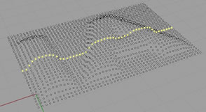
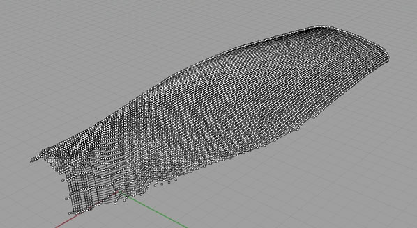
Below is the pointcloud of the letters IA (from the spanner) in Rhino. I have selected a line of them to make them stand out. From these points you can then create a 3D surface.. I just interpolated curves through rows of points before lofting a surface between the curves.
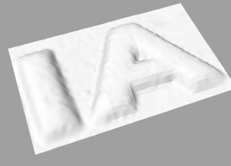
The image on the right shows a badly rendered version of the surface that was produced from the pointcloud to its left.

Better Mousetrap:
To get around the really slow digitizing speed I wrote my own digitizing algorithm. It is an adaptive feed plane method of sorts. Not sure if it is how they would do it in industry but it has seriously speeded up the process. The basic concept it to set a few parameters as before, the step over, the range and the speed. The probe then lowers until it hits the surface, it records the Z (it records the X and Y too but it should know those!). The probe then lifts a small distance, this could in theory just be until the contact is broken but I added a small offset to allow for potential surface roughness. The probe then attempts to move to the next point, if it gets there then it pecks again to find the z, if it hits something on the way then it lifts until the contact is broken (and adds the tiny safety offset) and moves off again. What this gives you is a probe that only lifts a short distance above the object, if the height changes then the probe ramps. For flat surfaces the feed plane is 0.2mm.
I programmed this up in C but unfortunately have not got it into a nice state for use by the masses. It is also slower than it should be and does not have ramping of the axis speeds etc.. Rather than do that I will probably (if I find the time) modify Turbo CNC to include the algorithm, the source is given to you when you pay the tiny (and well worth it) registration fee and Pascal is not so different from C.
I also wrote up a similar algorithm up that was thought up by Doug Fortune his idea was based on moving to the next point without lifting the probe. As long as the probe can handle that treatment (and most should for small steps) then that is OK. If at the new location the probe is still in contact then it lifts until contact it broken, this point can be taken as the z (or perhaps more accurately the surface can be probed again but from 0 height). This method worked well too but produces a lot of data potentially. You don't have to record every point but you do need to modify the height often unless you are confident that the probe can handle any possible tilts that might occur as a result of larger step overs.
I will hopefully return to some digitizing later and provide the source code for my algorithm and some test results to show the speed increase. Otherwise get TurboCNC and start programming!
Graham