Pictures and details of a 10" wingspan Buzzard.
I made this page to show some friends the progress as I developed the model in the summer of 2004, I had to halt developement due to having to write up my PhD thesis. I hope to return to it soon and produce a new test model where the geometry may be altered easily. Then I will try to make it look like a real bird again. I also want to sort out better shoulder joints.
History:
The model is based on plans for a 50cm span rubber model designed by Karl Herzog, based on the theory of E. V. Holst. You can read more about it on this great web page by Horst Räbiger.
I must also say that I came to try and build this model due to a desire to try something a bit different and try to improve on the simple membrane wings normally used. The greatest inspirations was RCgroups "Kaja" who build a lovely model based on the Holst's theories. Sadly he is no longer with us but it is well worth searching his user name or for Holst to see the models.
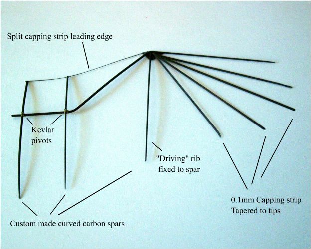
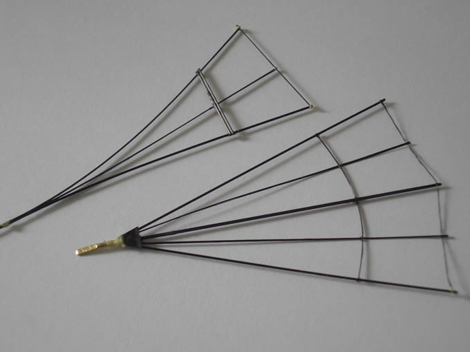
Weight of wing is 0.2g
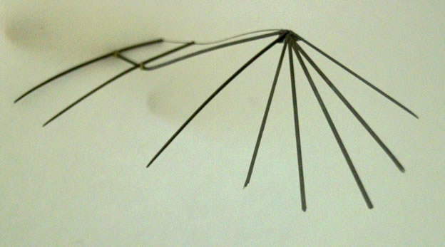
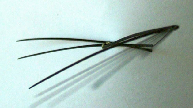
Notice the wing twist, the two inner ribs hing on the spar only the driving rib before the fingers is fixed to move with the spar rotation.

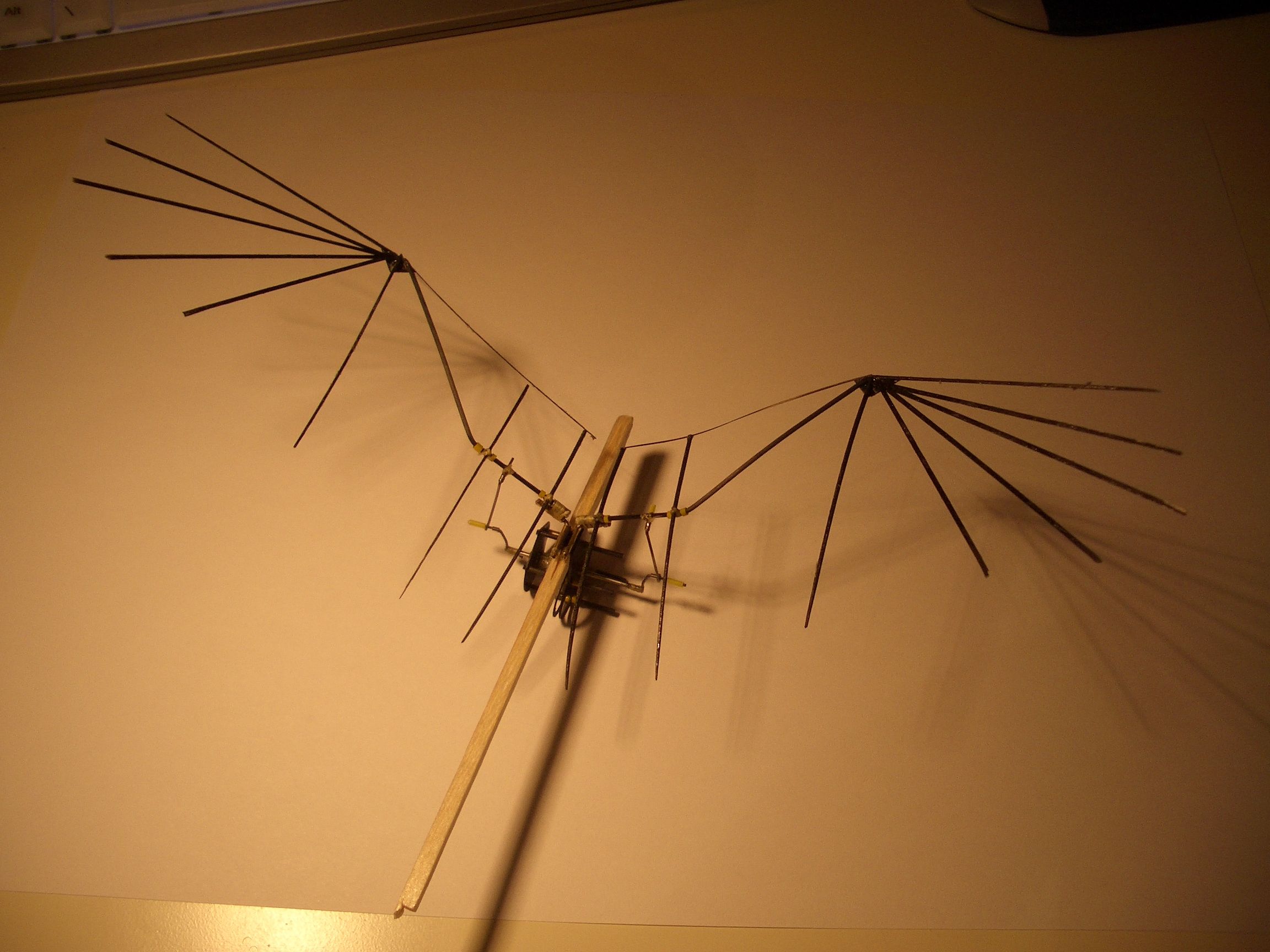
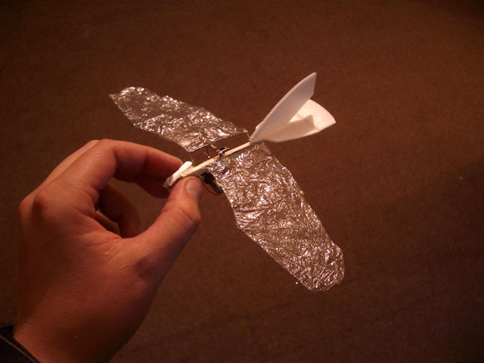
Wings now covered with 2g/m^2 mylar and mounted to a balsa stick for testing purposes. The glide is excellent and it really looks like a burrard as it does really flat circles. This was just to get an idea of the CofG. If nothing else I know I can make a model from these wings even if it turns out to be a glider :)

The gearbox has been constructed with a 64:1 ratio and so have the hinges and conrods etc, this is another test rig. Hopefully this will be used in a partial FF model and genrally to check the mechanism is durable and attempts to fly. Tail to be added.
WARNING, the following pics are large, 300kB each so if you wish to view you might prefer to right click and "save target as".
The gearbox from underneath showing the main shaft and crank arms.

The gearbox is constructed from 0.2mm thick carbon fibre plate and 1mm carbon rods. The motor is not shown and the motor holding tube is also not in place.
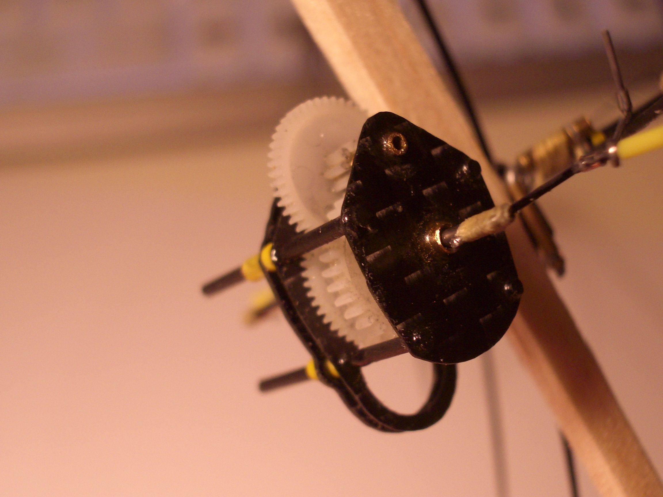
Short tubes of PVC hold the gearbox onto the carbon standoff (lowest carbon layer).
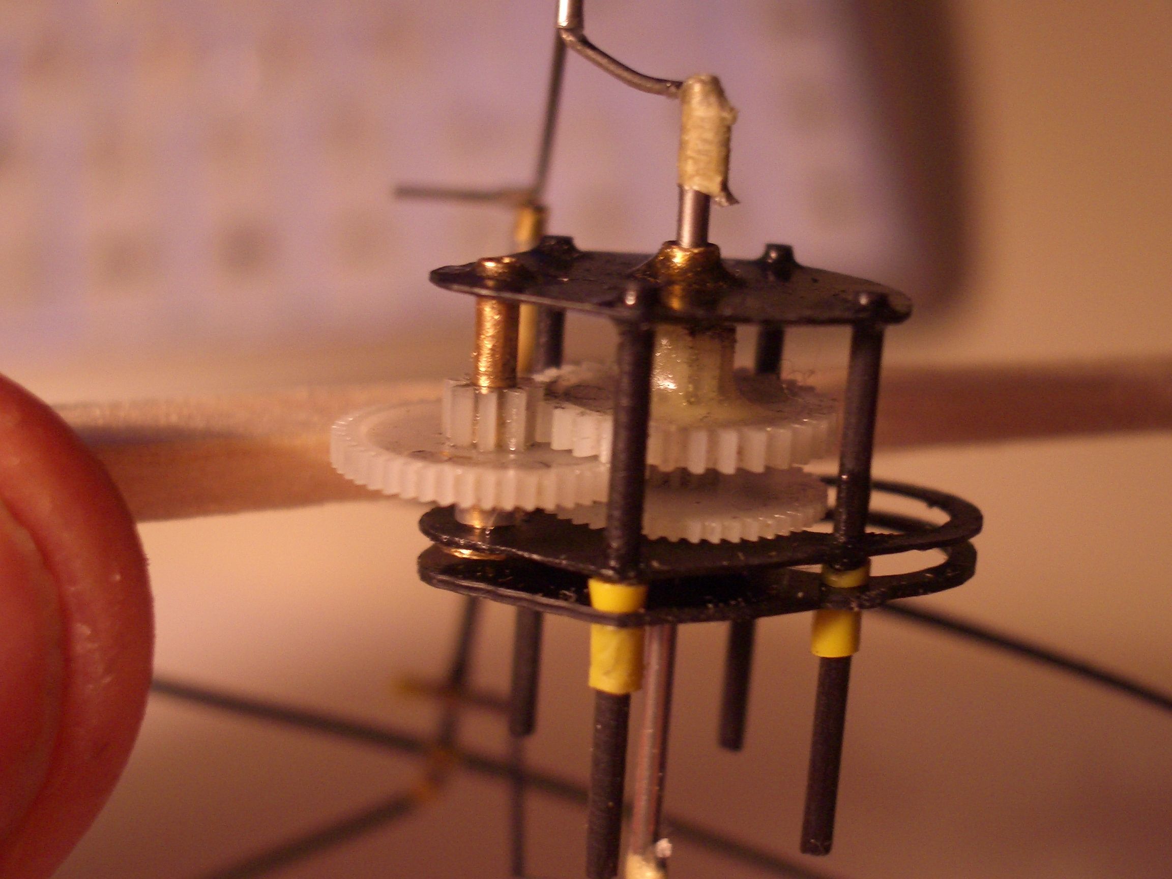
The cranks are bound to the shaft but engage with slots in the end made with a 0.17mm thick diamond wheel that I got from http://www.eternaltools.com MUCH better than the cheap disks.
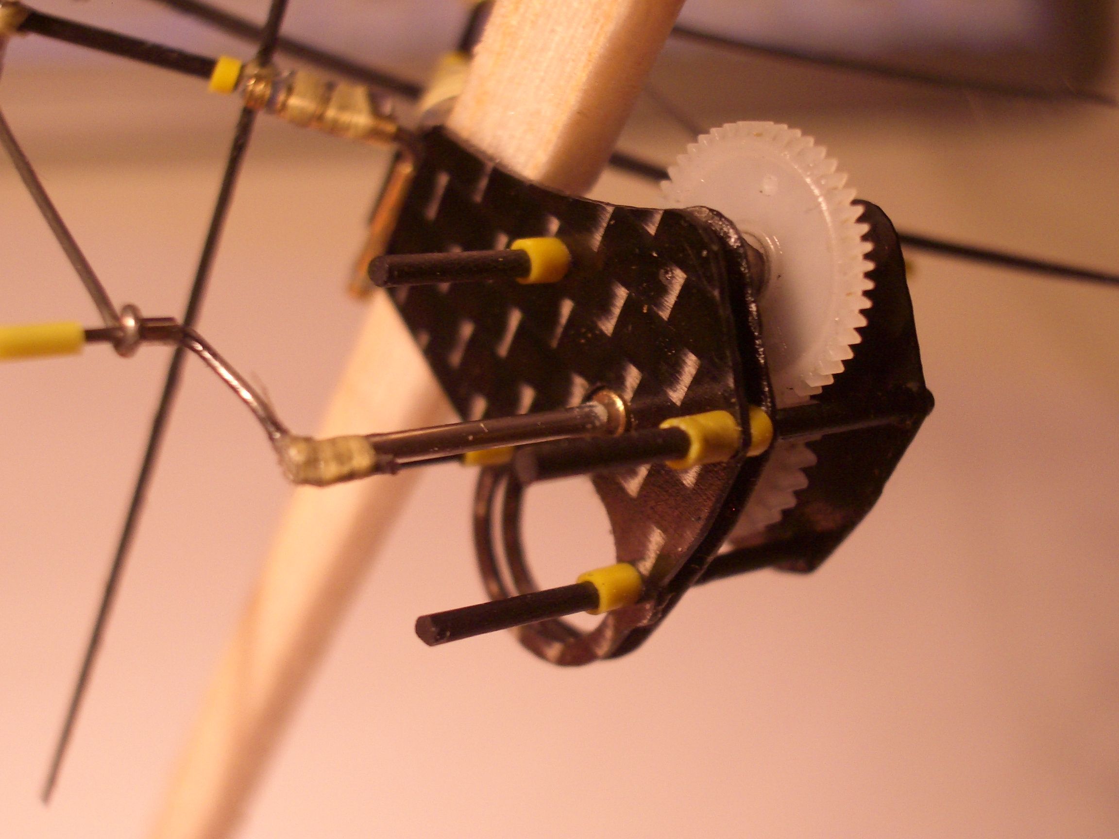
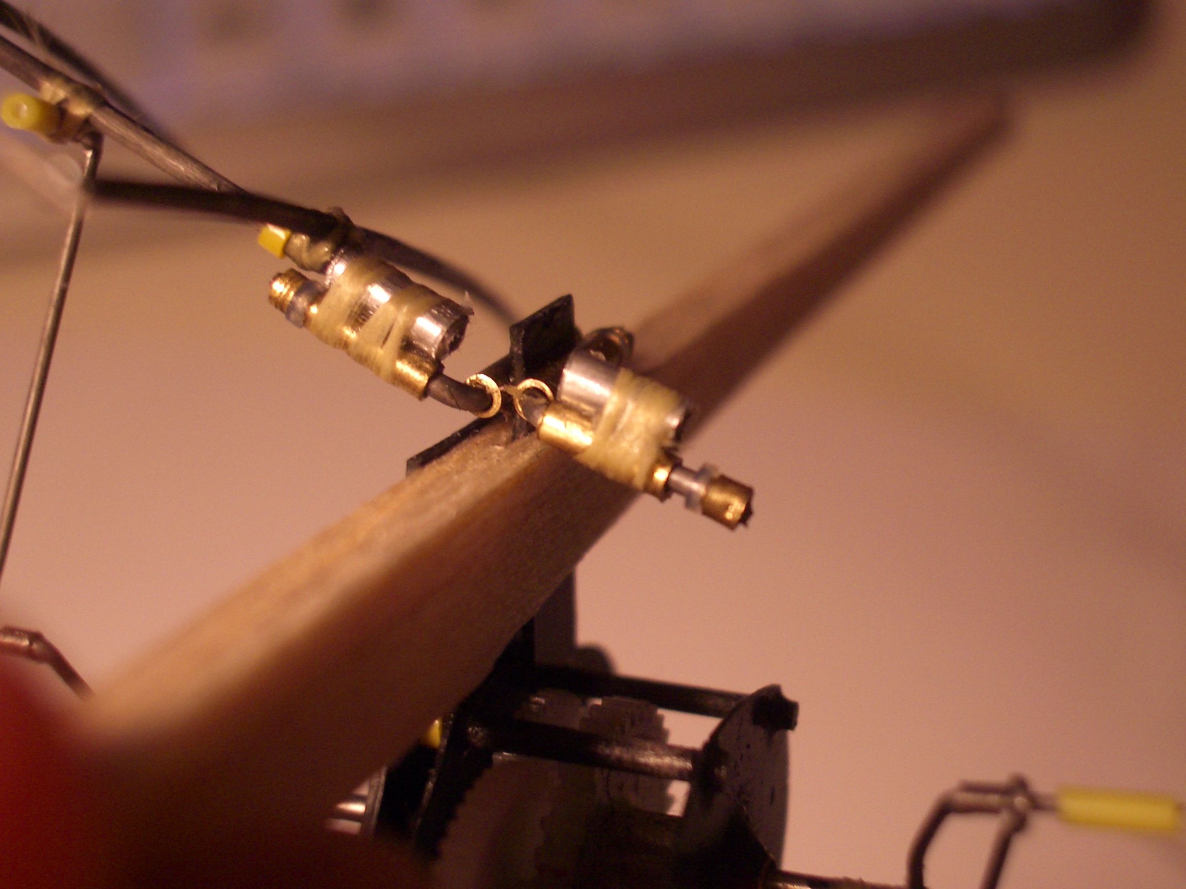
The shoulder hinges allow rotation of the wing and flapping but at the moment no sweep forward. Brass tube and wire are used for the hinges. Teflon tube is used for washers and short lengths of brass used as retainers. The wire is cut to provide a burr that also retains the brass tubing. The wings push into ali tubes at the moment.

The shoulder joints again, the left wing is disengaged from the conrods. The L in the crank produces the twist in the wing during the flap..
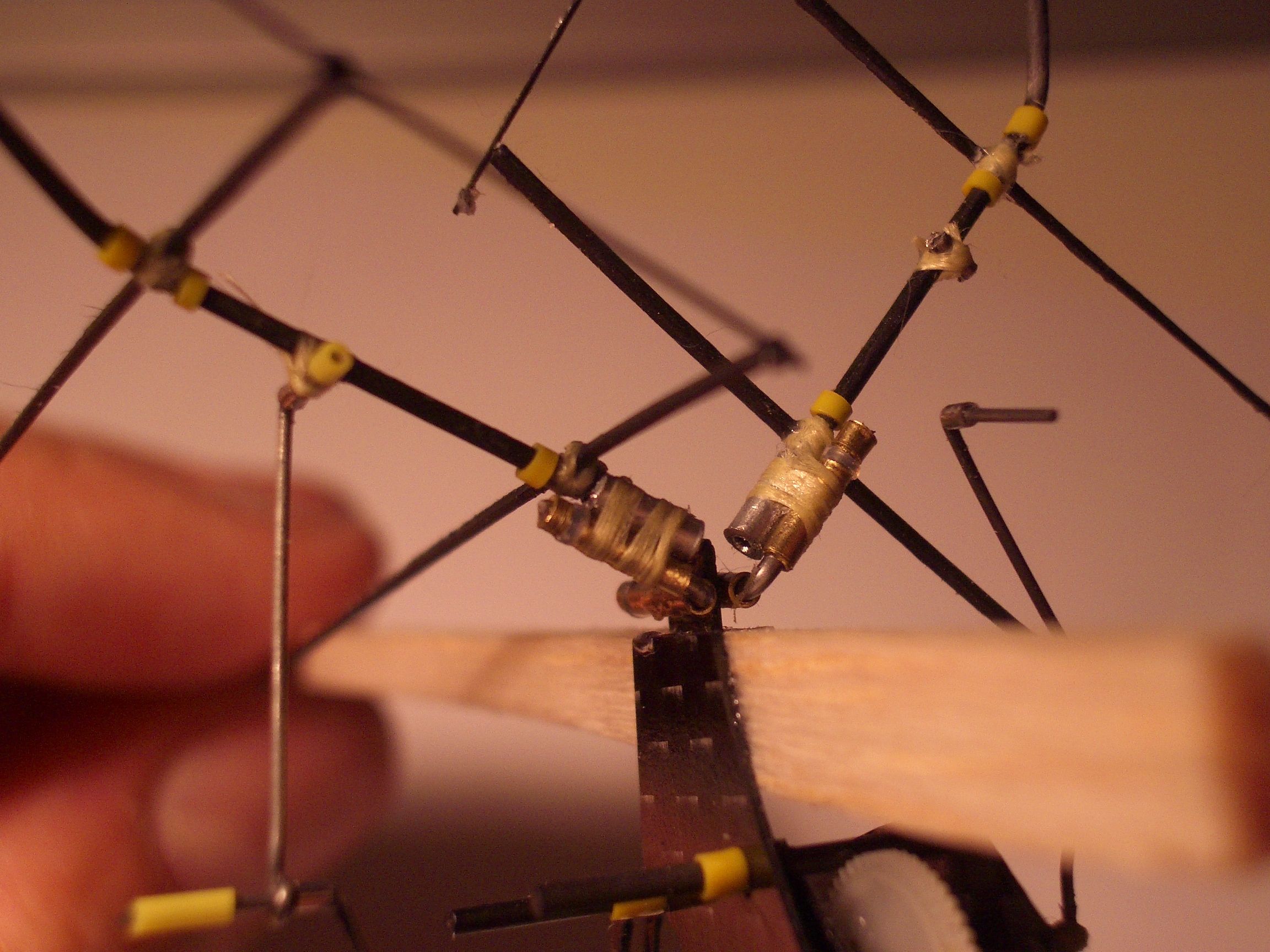
The same joint with wing removed.
Another test rig:
I built up an IR receiver at 0.3g and have now mounted that to the test rig and re-covered the wing. A 2mm Depron tail has also been added. Some static flap tests have been performed, these showed a flap frequency of 5hz and a thrust of 2g. The test was at 3.7v and the motor was drawing 100mA. As the motor can handle 400mA this may suggest the gear ratio of 64:1 is too high, however the wingspan is quite large to the projected weight.
To see the rig in motion I built the following test rig:
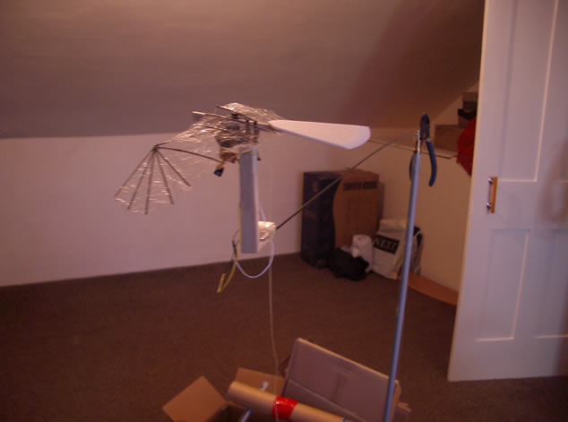
I do not suggest that scientific measurements can be taken from this set up however it is interesting to watch. The upright is from a broken lamp and the central bearing from a video recorder. The arm is 2mm carbon and the counterweight a pair of pliers. The model simply clips onto the top of the balsa upright and can propel itself around a circular path. To my suprise it picked up quite a speed but of course it is not supporting it's own weight. Further modifications to the rig could be made to allow more meaningful results but for now this video is enough.
Video of buzzard on test rig (1.04Mb right click and "save target as")
Slight improvement, added a platform for my camera in the centre of the rig, that spins with the model:
Video of buzzard on test rig from centre (2.32Mb right click and "save target as")
Yet another test:
The cell has now been added to the model, I had to use the 90mAh Etec rather than the 60mAh Kokam to get the CofG correct. I also switched the gearbox around to move the motor forward on the model. After several failed test glides and much tweaking I got something that looks pretty good:
Video of Buzzard powered glide: (288kb right click and "save target as")
Main things were a tweak to ensure the incidence is always positive and the addition of a fin. The test was at full power, I think this is basically telling me that the gear ratio is too high, no suprise considering the 100mA draw. I will persist a little knowing trim is critical but otherwise will make another gearbox. They slot in after all!!
Gear ratio change: lowered the ratio to 36:1, now using Didel gears. Flap rate is up and I was expecting sucess but decided to try and improve battery mounting ready for the Nunthorpe lying session. This is what resulted:
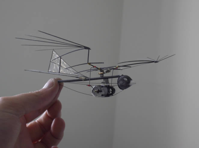
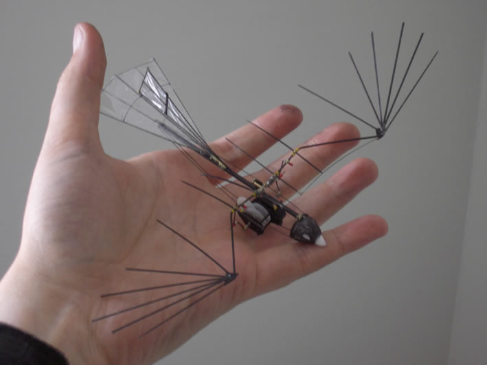
The head is just white foam crudely carved and has to be removed for flight as the battery needs to fit right at the front for the correct CofG. The spine is some homemade carbon tube made with fine brade over a balsa rod which was later removed, very light stuff! The tail is all split carbon rods, the fin is actually made from a single rod split lengthways and bound with a turn of kevlar to stop the split, looks kind of nice. The two vertical rods are where the hinges will be when rudder control is added.
Flight report:
At the Nunthorpe meet I had very little sucess, I had never been able to get the stable glide I had been used to with the test model. Further investigation showed that the problem was simply poor wing covering, I had put it on too slackly, not normally a problem for ornithopters but as this has a full set of ribs and relys on the wing acting like a wing rather than a rogollo type affair it needed to be tighter. Further tests showed better stability but no climb, in fact a degraded climb over the test model with 64:1 gear ratio despite it being lighter. There is a chance that the cell is bad but I suspect there was a slight change in geometry when assembled in the current form. The assembly was actually more accurate this time so perhaps I was lucky the first time.